SHERLOCK AMPLIFIERS
MIDI MOD INSTALLATION INSTRUCTIONS
DESCRIPTION
The MIDI MOD is a single chip, micro controller PCB, designed to receive program change information only from any MIDI transmitting device i.e. MIDI foot controller, sequencer etc. and on any MIDI channel. Installed into a guitar pre-amp for example which is required to be MIDI driven, allows pre-amp function i.e. channel changing, EQ. in or out to be activated via MIDI command. Up to 8 pre-amp functions can be controlled simultaneously per program number and stored in MIDI MOD’s non volatile RAM.
SPECIFICATIONS
*SINGLE CHIP micro controller technology
*100 PROGRAM numbers
*CONTROLS 8 functions simultaneously
*4 OPERATING MODES for control
*MIDI IN responds to program change information only
*MIDI THRU echoes MIDI in data
*MIDI CHANNELS receives on 16 MIDI channels
*POWER REQUIREMENTS 7vac @ 150ma or +5vdc regulated
*NO BATTERIES REQUIRED for memory retention
*SMALL COMPACT SIZE (105mm x 61mm x 25mm) for easy installation
POWER SUPPLY
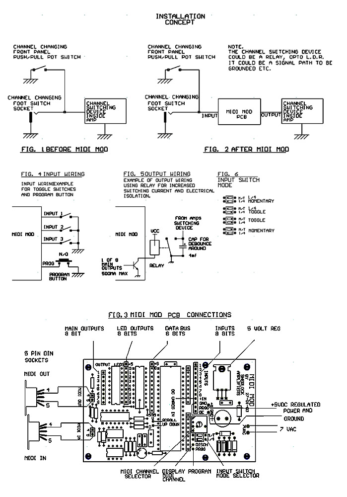
MIDI MOD requires approx 7 volts AC at about 150ma to power its own +5 volt regulator circuit fig.3. If available, this power should be taken from the unit the MIDI MOD is being installed into. Alternatively, if the unit has a +5 volt regulated supply available, the MIDI MOD can use this with no problem as its current draw is minimal. The power supply section of the MIDI MOD can be cut off if not used to reduce the pcb size. If the MIDI MOD has to switch relays, fig.5 this additional current must be taken into consideration.
If the MIDI MOD is to be installed into a valve head or combo without the correct voltages available, then another power transformer of around 7-9 volts, 150mA will have to be installed.
INPUTS
The MIDI MOD has 8 inputs for control purposes. All inputs are held high and are clearly labeled 1 to 8 on the PCB and the main wiring instructions. Fig.3
When any of the inputs are brought low, the corresponding outputs will turn on also. Input switches can be either toggle, momentary or rotary.
INPUT SWITCH MODE
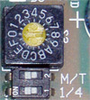
The MIDI MOD's mode switches labeled M/T and 1/4 will have to be set depending on what type of input switches are used. 4 different modes are available to cater for all switching requirements.
TOGGLE MODE
If input switches are toggle switches, a switch on a push/pull pot or a rotary switch, this mode should be used. The MIDI MOD's outputs will be on or off depending on whether the switch is on or off. See fig.6 to set this mode.
MOMENTARY MODE
This mode allows the MIDI MOD's input to be operated with normally open momentary action push button switches, i.e. press the switch once and the corresponding output will turn on. Press again and it will turn off. See fig.6 to set this mode.
1 OF 4 MODE with TOGGLE
This mode allows the MIDI MOD's inputs 1,2,3,4 to operate like a 4 way mechanical push button switch. Pressing one button will turn off the button previously pressed, so there is only ever one button or output on at any one time. The other inputs 5,6,7,8 operate in the toggle mode. This mode is usefully if installing MIDI MOD into a three or four channel pre-amp where only one channel is to be on at one time. See fig.6 to set this mode.
1 OF 4 MODE with MOMENTARY
The last mode is the same as the previous mode only the inputs 5,6,7,8 operate in momentary mode. See fig.6 to set this mode.
PROGRAM SWITCH
A momentary action push button switch is provided for storing programs, and can be mounted either on the front or rear panel. Using the normally open set of contacts wired to the P connection as shown on wiring instructions. fig.4
OUTPUTS
The MIDI MOD has 3 sets of 8 bit outputs.
DATA BUS OUTPUTS
The first set is an 8 bit data bus labeled H2 (BUS). In addition to the data bus there is also +5vdc (+5), ground (G) and a strobe line (S). Connections are in the form of an 11 way header.
The data bus is to be used with the display board (optional extra) and will output the program number MIDI MOD is on.fig.3
LEDS OUTPUTS
The second set of 8 bit outputs labeled H3 (LEDS) can be used to drive led status indicators, giving visual indication of which outputs are on or off. These outputs can source up to 25mA each. Connections are a 9 way header, 8 data bits and ground (G).
MAIN OUTPUTS
The third set of 8 bit outputs labeled 1 to 8 are the main outputs labeled H4 (OUTPUT). These are used to switch the functions of the unit the MIDI MOD is being installed into and are an open collector transistor array capable of sinking 500ma at 50v each. If additional switching currents and or electrical isolation is required, these transistors should be used to drive opto devices, relays etc. fig.5
NOTE: Different output wiring combinations are possible i.e. a three channel pre-amp can be wired directly with each output of the MIDI MOD controlling each channel separately or two outputs from the MIDI MOD can be used providing a binary code which would be fed into the pre-amps A B digital switching inputs. This method allows the MIDI MOD to control more function because it uses 2 outputs instead of 3.
MIDI IN
The MIDI MOD has a serial data input port i.e. MIDI in.
A 5 pin din socket with mounting hardware is provided and should be installed on the rear panel somewhere. Two wires from pins 4 and 5 are brought to the MIDI in pins labeled 4 and 5 on the MIDI MOD pcb as shown on wiring instructions. Fig.3
MIDI THRU
The MIDI MOD has a MIDI thru output if required. This output echoes MIDI data as it is received from the MIDI in port and is generally not required. However, if required, this can be used by connecting a 5 pin din socket (not supplied) as shown in Fig.3
MIDI CHANNEL SELECTOR SWITCH
The MIDI MOD can receive program change information on any of the 16 MIDI channels. The table below shows the correct switch settings for the MIDI channels
| SWITCH LABELLING |
MIDI CHANNEL |
Midi channel switch and Input Mode switches |
0 1 2 3 4 5 6 7 8 9 A B C D E F |
|
|
MIDI MOD INSTALLATION
The MIDI MOD is generally easy to install, but a few precautions should be observed for a successful, reliable noise free installation.
1. Anti-static precautious should be observed when handling the MIDI MOD pcb as all chip are of the CMOS variety.
2. The MIDI MOD pcb should be located as far away as possible from heat sources such as valves etc. and away from mains and output transformers.
3. Installation should be done in such a way that ground loops etc. are not created. Keep the MIDI MOD's ground separate from the audio ground and only join them at the power supply or chassis. The MIDI MOD's outputs should, if possible, be electrically isolated from the audio circuitry by a relay, or some sort of opto coupling device. Most modern pre-amps, heads, etc. us some sort of opto coupling device (light cell) for switching and MIDI MOD's outputs can be directly connect to these.
Most channel switching is done via foot switch sockets on the front or rear panel or a push/pull pot on the front panel of the amp. Fig.1 The wiring to these sockets/pots must be broken and MIDI MOD installed in between them. Fig.2
EXAMPLE
A two channel amp will have one foot switch socket or maybe a push/pull pot for channel changing. Fig.1 Grounding this socket will change the amps channels from say clean to lead. The wire from this socket or push/pull pot (inside amp) will be disconnected from where it went to and taken to input No.1 of the MIDI MOD. The corresponding MIDI MOD output, No.1, will be wired to the point where it was taken from. Fig.2 via an isolating device such as a relay, Input switching mode is set to toggle. So now when you ground the socket as before, input No.1 goes low causing output No. 1 to turn on (relay) and in turn activating the switching device which changes the amps channels.
WARNING: care must be taken to ensure that the maximum sink currents the MIDI MOD is required to handle from the amps channel switching device are not exceeded (500ma max @ 50v per output). If they are, a buffer circuit of some description will have to be used. A possible circuit is shown in fig.5 of the wiring instruction.
Additional switching functions should be wired the same way.
Once MIDI MOD has been installed refer to the operating instruction below.
PROGRAMMING THE MIDI MOD SWITCHER
WITH A FOOT CONTROLLER
- Select a patch number on the midi controller or sequencer (1-100)
- Select the amps channel or function using the corresponding buttons on the Midi Mod. The led or leds on the Midi Mod will light up to indicate which channels or functions have been selected.
- Press and hold the PROG button for 2 seconds. The Midi Mod will now save this combination and assigned it to the patch number selected on the foot controller (in step 1), and your done.
- To check your programming has been successful, select another patch number on the Midi controller and then select the one you selected in step 1, and the Midi Mod switcher will recall your programmed combination.
Contact:
Sherlock Amplifiers
Phone: 03 98916054
Email:info@sherlockamps.com
Website:www.sherlockamps.com

